Many contractors in Cincinnati assume the dense glacial till found across the city provides uniform bearing conditions everywhere. That assumption fails on infill sites along the Ohio River floodplain or former industrial yards in the Mill Creek Valley. We have seen projects where loose granular fill over soft alluvium caused 30 mm differential settlement within six months of slab placement. Without proper dynamic compaction design, the energy applied either under-treats deep loose zones or over-treats competent layers. A site-specific energy grid, drop weight, and grid spacing must be calibrated to actual soil profiles. Before mobilizing a crane, we cross-check the target depth against asentamiento diferencial records from nearby sites in Cincinnati. That historical data refines the initial energy per unit volume calculation.
Dynamic compaction design in Cincinnati must account for variable fill thickness, shallow groundwater, and the transition from glacial till to alluvium.
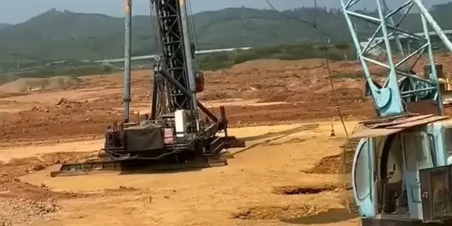
Technical details of the service in Cincinnati
Critical ground factors in Cincinnati
Cincinnati sits at 147 m elevation above sea level, but the Ohio River can rise 15 m during a 100-year flood event. That floodwater saturates the loose granular fills common in the East End and Riverside neighborhoods. When dynamic compaction design does not account for near-saturation conditions, pore pressures build rapidly and the drop energy dissipates into water instead of soil densification. The result is a treated zone that looks compacted on the surface but remains loose below 3 m. We have cone penetration test data from the I-75 reconstruction corridor showing tip resistance below 3 MPa in post-compaction zones that missed saturation correction. To avoid that, we use a high-permeability drainage layer and apply a 2-week rest period between passes when the water table is within 2 m of the surface.
This service complements our laboratory testing work for a complete project analysis.
Our services
We deliver three specific services within dynamic compaction design for Cincinnati ground conditions.
Energy Grid Design
We compute the optimal tamper weight, drop height, and center-to-center spacing using site-specific SPT N-values and fill thickness. The output is a phased grid map with primary, secondary, and ironing pass coordinates.
Instrumentation and Verification
After each pass, we perform cone penetration tests and nuclear density gauges to confirm relative density and modulus improvement. We compare results against the acceptance criteria defined in the project geotechnical report.
Wick Drain Integration
For sites with high water table, we design and install prefabricated vertical drains (PVDs) before compaction to accelerate pore pressure dissipation. The drain spacing is calculated based on the coefficient of consolidation from laboratory oedometer tests.
Quick answers
What is the typical cost range for dynamic compaction design in Cincinnati?
The cost for dynamic compaction design in Cincinnati typically ranges between US$1.340 and US$4.520 for a standard residential or light commercial lot. This includes field testing, energy grid calculation, and verification testing. Larger industrial sites with multiple passes can exceed that range.
How deep can dynamic compaction treat Cincinnati soils?
In the Ohio River valley, dynamic compaction effectively treats loose granular fills down to 6-8 m using a 20-ton tamper dropped from 25 m. On the glacial till uplands (e.g., Mount Auburn, Clifton), improvement depths are shallower, around 3-5 m, because the base material is stiff. We always verify with post-compaction borings.
Is dynamic compaction suitable for clay soils in Cincinnati?
Dynamic compaction works best in granular soils. For the high-plasticity clays found in the Kope Formation (southwest Cincinnati), the method has limited effectiveness because pore pressure dissipation is slow. For those zones, we recommend preloading with wick drains or a precarga program combined with surcharge fills.
How does dynamic compaction affect nearby structures in Cincinnati?
Vibration from a 15-ton tamper at 20 m drop generates peak particle velocities of 5-15 mm/s at 15 m distance. That is below the 50 mm/s threshold for cosmetic damage per USBM RI 8507. For sensitive buildings near the site, we install vibration monitoring arrays and can reduce drop height or use a cushioned tamper.